

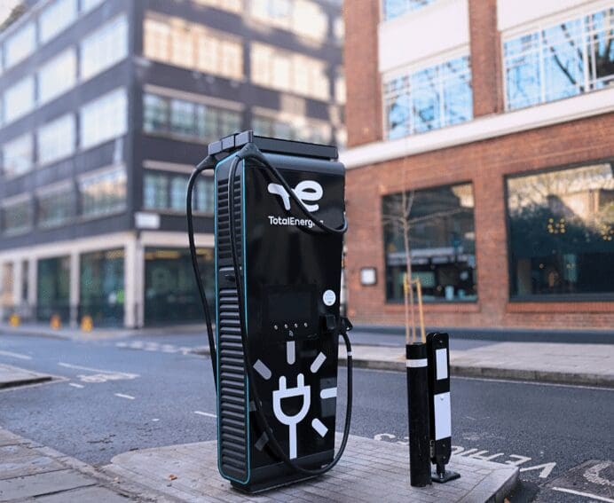
The race to make electric vehicle charging faster is gathering pace. Higher-voltage vehicle platforms, more powerful charging stations and the emergence of megawatt-scale systems promise to reduce the time drivers spend waiting at charging stops.
Earlier this year, EV Powered reported on Ionity’s first European megawatt charging installations, where individual charging points can deliver up to 600kW from a shared power system.
Yet behind these impressive figures lies an engineering challenge that rarely features in charging-speed announcements: heat.
A high-power charging station must do more than deliver electricity quickly. It must manage the heat generated by its own power electronics, often while operating outdoors, serving consecutive vehicles and coping with changing environmental conditions.
As charging power increases, thermal management becomes a critical part of the system’s efficiency, performance and long-term reliability.
Where Does the Heat Come From?
Unlike a conventional AC charging point, a DC fast charger converts alternating current from the electricity grid into direct current suitable for charging a vehicle’s battery.
This conversion takes place inside the charging equipment, typically through power electronic stages containing semiconductor switches, rectifiers, magnetic components and other electrical hardware.
Modern chargers increasingly use advanced power semiconductors, including silicon carbide (SiC) devices, to support high-efficiency power conversion.
However, no conversion process is completely loss-free.
Consider a simplified example: if a charger’s power conversion stage delivers 350kW at 97% efficiency, approximately 11kW is lost during conversion.
That is a substantial amount of heat for the equipment to manage, even though the conversion stage is operating efficiently.
Actual losses depend on the charger’s design, operating conditions and efficiency at a particular load. Heat is also generated in other parts of the electrical system, including cables and connections.
The challenge becomes more demanding as charging systems scale towards megawatt-level power and higher utilisation.
Why Heat Matters to Charging Performance
A charger’s power rating tells drivers what it can potentially deliver, but it does not guarantee that the maximum output will be available throughout every charging session.
The vehicle’s battery temperature, state of charge, battery management system and charging architecture all influence how much power a vehicle can accept.
There is also a separate consideration on the charging-station side.
Power semiconductors and other electrical components have defined operating temperature limits. If temperatures approach these limits, the equipment may need to reduce its output to protect critical components.
This protective reduction in power, known as thermal derating, is one reason thermal design must be considered alongside the electrical design.
It is important to distinguish charger thermal limitations from the normal charging curve of an EV battery. A charging rate that falls as the battery fills does not, by itself, indicate a problem with the charging station.
Nevertheless, effective cooling helps ensure that the charging equipment itself does not become an unnecessary restriction.
The Important Role of Heat Sinks
Inside a fast charger, heat generated by power semiconductor modules must be transferred away from sensitive components and ultimately released into the surrounding environment.
A typical cooling path begins at the semiconductor module, passes through a thermal interface and a metal cooling structure, and then transfers heat into air or circulating liquid.
Aluminium heat sinks are widely used in power electronics because they combine useful thermal conductivity with relatively low weight, manufacturing flexibility and cost efficiency.
An aluminium finned heat sink used for thermal management in power electronics.
Depending on the charger’s construction, the cooling system may use extruded aluminium heat sinks, high-density fins, fan-assisted assemblies or more complex structures.
However, simply adding more fins is not necessarily the answer.
A heat sink must suit the available airflow, the position of the heat sources and the operating environment. Closely spaced fins can increase heat-transfer area, but they can also restrict airflow if the fan system cannot overcome the additional resistance.
The contact between the power module and its cooling surface is equally important.
Poor surface flatness, excessive thermal interface material or uneven mounting pressure can increase thermal resistance, making it harder for heat to escape from the semiconductor.
For manufacturers developing power electronics cooling solutions, these mechanical details are just as relevant as the size and shape of the heat sink itself.
A successful design needs to consider the complete thermal path rather than treating the metal cooling component in isolation.
Air Cooling or Liquid Cooling?
Air cooling remains a practical approach for many charging applications.
Its advantages include relatively straightforward construction and the avoidance of pumps, coolant connections and liquid circuits. With suitable heat sinks and forced airflow, air-cooled systems can provide effective cooling for a wide range of power conversion modules.
However, air cooling becomes more challenging when heat is concentrated into a small area or the equipment has limited space for ventilation.
This is where liquid cooling may offer advantages.
A liquid cold plate is positioned against the heat-generating components. Coolant flows through internal passages in the plate, carrying heat away to a radiator or another heat exchanger elsewhere in the cooling system.
A machined-channel aluminium liquid cold plate, shown before assembly.
Because the coolant can remove heat directly from a compact region, liquid cooling can be particularly useful for densely packaged power electronics.
Some higher-power charging architectures also extend liquid cooling beyond the power modules to other parts of the system, including charging cables.
But liquid cooling introduces its own engineering requirements.
The design must account for coolant flow, pressure drop, leak prevention, material compatibility and long-term maintenance. A poorly designed cooling loop can create reliability problems of its own.
The construction of the cooling plate also matters. Different approaches to liquid cold plate manufacturing can offer different combinations of thermal performance, manufacturing complexity and cost.
The right choice depends on the actual heat load, available space, cooling conditions and operating requirements—not simply whether a system is described as air-cooled or liquid-cooled.
Outdoor Conditions Add Another Challenge
Public charging stations are expected to operate throughout the year, often in environments that are far less controlled than a factory or laboratory.
High summer temperatures can reduce the temperature difference available for air cooling. Dust, dirt and blocked ventilation paths may further affect cooling performance.
Meanwhile, moisture protection and the need for robust outdoor enclosures can place additional restrictions on airflow and equipment packaging.
Charging stations at busy motorway services or commercial vehicle depots may also experience repeated high-power sessions with relatively little idle time between them.
Designing for a short peak-power test is therefore not the same as designing for continuous or repeated operation over many years.
Engineers need to evaluate cooling performance under realistic operating conditions, including high ambient temperatures, repeated load cycles and the effects of ageing or maintenance requirements.
Temperature sensors, fan monitoring and coolant-flow monitoring can help detect developing problems before they result in a complete shutdown.
Reliability Is Becoming as Important as Charging Speed
For chargepoint operators, charging performance is only part of the commercial equation.
A high-powered charger that is frequently unavailable can undermine driver confidence, create maintenance costs and reduce the value of the infrastructure investment.
In the UK, the Public Charge Point Regulations require operators to achieve an annual average reliability of 99% across their networks of qualifying public rapid chargers.
Achieving dependable operation involves far more28 than thermal management alone. Software faults, payment systems, communications, connectors, electrical protection and maintenance practices can all affect charger availability.
Nevertheless, thermal design is one of the factors manufacturers can directly address during equipment development.
Effective heat removal, carefully designed component interfaces and appropriate cooling-system monitoring can help power electronics operate within their specified limits.
This becomes particularly important as public charging networks expand and high-power equipment is expected to deliver more energy over longer operating periods.
The Engineering Behind the Next Generation of Charging
From the driver’s perspective, the future of EV charging is straightforward: shorter stops, predictable charging speeds and equipment that works when needed.
Delivering that experience is much more complicated.
As charging stations become more powerful, engineers must balance electrical efficiency, semiconductor performance, thermal design, mechanical packaging and maintainability.
More efficient power electronics can reduce the amount of waste heat generated, while suitable heat sinks and liquid cooling systems help manage the heat that remains.
Neither approach can replace the other.
The next generation of ultra-fast chargers will be judged not only by their headline power ratings, but also by how consistently they perform in everyday use.
Much of that performance will depend on engineering decisions hidden inside the charging cabinet—long before a driver plugs in.


